

Making Progress in the Automotive world
Delivery time of more than one year for a forming tool in the automotive sector - This unusual schedule is only feasible when the tool supplier is heavily involved with the automotive manufacturer, even before the first prototype crash tests are performed.
Based in Heiligenstadt, Germany, Rosell Werkzeugbau & Stanztechnik GmbH have recently moved to new premises and extended their production area from 1120 m² to 4500 m². The company are experts in the metal stamping industry and specialise in research & development, tool manufacture and project management for the automotive field. In addition, the company also supplies tools for the domestic, computer and medical sector.
"VISI was a quantum leap from the software that we had installed previously. It is easy to notice the progress we have made since switching to VISI and 3D tool design”
Franz Rosell
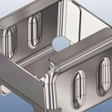
In a recent project for the Audi Q5, Rosell, in partnership with their customer Griwe Werkzeug Produktions GmbH, a supplier of AUDI AG developed a progressive tool for the retainer sill, which is located under the B-column. The retainer sill was to be produced using high-strength steel with a tensile strength of 1000 N/mm².
"Working closely with the customer is an important part of our tool development" explains Franz Rosell, managing director of Rosell Werkzeugbau & Stanztechnik GmbH. "Once the order has been received, we complete a strip layout and preliminary design for all forming stations and present the data to our customer". Franz explains that previously such presentations took about an hour; "Historically, the customer was presented with a pile of A0 drawings that were used to detail the project. It was extremely difficult to present how the tool would operate and explain the critical ideas of the tool maker." Today, Franz Rosell must schedule at least three hours for such a meeting as a 3D representation of the tool provides the customer with a much clearer idea of the tool mechanics and the technical discussions go into much more detail.
Close to the tool maker
All tool design & manufacture is performed using VISI from Vero Software and has been in place at Rosell since 2003. "VISI was a quantum leap from the software that we had installed previously," explains Franz Rosell, "unlike the old software, VISI is close to the tool maker. All our designers are fully trained, but almost all staff members are able to work with VISI. There are approximately eight or nine other engineers who are able to use VISI to extract the relevant information they need from a model."
The initial tool design is based around three typical steps :
Step #1
The first step is to develop the 2D blank shape from the 3D model. This is done using VISI Blank, an integrated solution that provides valuable analysis of material behaviour during the forming process such as 'thinning' and "wrinkling" allowing accurate identification of potential problem areas prior to physical die design. Franz Rosell explains that previously the blank development was calculated using a collections of tables which often led to a considerable number of errors. Today, blank calculation is based on a material database that includes material strength, density, work hardening rate and yield stress.
Step #2
With the blank development complete, the second step is the design of the bending / forming stages and the production of the 3D strip using VISI Progress. Step by Step unfolding allows the designer to plan each forming stage by dynamically adjusting bend angles allowing complete freedom for unfolding experimentation. Once the forming stages are complete, it is possible to automaticaly generate a 2D strip plan which forms the basis of the 3D strip. Tools such as automatic blank alignment and nesting help plan a more efficient strip and provide the engineer with valuable information such as material wastage. The 3D strip can be simulated at any point to validate the performance of the punching and forming stages.
Step #3
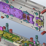
When the customer is satisfied with the tool process plan, the 3D tool design can begin. The tool design must be approved by the customer and it is here that the main difference between the old 2D style presentations becomes most apparent. Franz Rosell presents the tool in the form of individual plate components and 3D details are often adjusted 'live' together with the customer. Once the customer has approved the 3D design, the standard components such as screws, dowels, strip lifters and springs are integrated into the design. Finally, the designer uses the 3D model to automatically generate the 2D views of individual components.
Design to manufacture
The die plates for the tool are pre-milled directly from the 3D model and then sent for hardening in vacuum furnaces where the plates are put through a secondary hardening process. This allows the plates to be coated afterwards without exceeding the tempering temperature of the steel. Typically steel is heat treated in a multi-step process. First it is heated to create a solid solution of iron and carbon in a process called austenizing. The steel is then rapidly cooled and finally tempered by heating again between the ranges of 150°C-260°C (300°F-500°F) and 370°C-650°C (700°F-1200°F). The steel is then held at that temperature until the carbon trapped has been diffused - the result is nearly pure ferrite and the steel becomes strong and ductile.
Die apertures are machined using Wire EDM which allows the operator to cut intricate contours or internal corners with very small corner radii based on the wire diameter and spark gap. Spark emissions create a white layer that is subsequently blasted with glass beads to produce a clean finish, without any dimensional change to the part and remove any light burrs from the plate or insert.
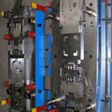
The forming tools that shape the component are hardened after pre-milling with a material oversize allowance and then hard-milled to size using VISI Machining, a powerful 3D CAM solution that can be used either in the CADCAM office or the shop-floor. The old 2D designs made it very difficult to see whether a form part would jam during the assembly. Having a 3D model of the tool assembly allows the engineer to easily check the relationship between the individual parts. A VISI viewer has been installed in the assembly workshop for this exact purpose. The tool maker cannot change the data, only interrogate the model in 3D and extract the relevant measurements or create plots if necessary.
Fine-tuning
Fine-tuning of the tool starts with data produced using VISI Blank. This is used to drive a laser to cut a preliminary strip that is then formed and separated inside the tool. This ultimately creates a prototype component that simulates all cutting, bending and forming operations. The final component is scanned using a CNC co-ordinate measuring machine and quality checked against the target model provided by the customer. If any deviations are detected between the target and the actual model, the changes are filtered back through to the 2D blank and a new strip is cut with the laser and formed until the deviations are within acceptable tolerances.
Finally, the completed tool is assembled and a pressing date is arranged with the customer with the production part again being checked with a co-ordinate measuring machine. On occasions, different moulding presses can generate different conditions and tolerances in the tool, so any last minute fine-tuning may take place on-site.
Franz Rosell concludes, “It is easy to notice the progress we have made since switching to VISI and 3D tool design. We have an excellent relationship with the software distributor, Mecadat, and the products have established themselves as an integral part of our future plans."
About The Company:
Name: Rosell Werkzeugbau & Stanztechnik GmbH
Web: www.dynamic-italia.it
Benefits Achieved:
- Automatic blank development based on material strength, density, work hardening rate and yield stress
- Efficient strip design with minimal material wastage
- Automatic 2D CAD drawings
- Direct link to manufacture for Wire EDM and 3D HSM machining
"VISI was a quantum leap from the software that we had installed previously. It is easy to notice the progress we have made since switching to VISI and 3D tool design”
Franz Rosell


